~Ajith S Ramani and Abdelrahman H. Ahmed. 10/2016 ~
RTL Compiler is an HDL synthesis software from Cadence.
1 Cadence working directory setup for GPDK
This step is to be done only one time for the same user’s account. The purpose of this step is to prepare the environment for all the Cadence-based tools. In your home directory execute the following:
| >> mkdir Cadence_StudentNumber >> cd Cadence_StudentNumber >> source /CMC/kits/AMSKIT616_GPDK/underg_install.csh |
Note that after sourcing “underg_install.csh” some folders and a “.csh” file will be created in the “Cadence_StudentNumber”. In your future use for any of the Cadence tools you will descend into the corresponding folder and in all cases you will source the same “.csh” file.
2 Environment Setup and starting RTL Compiler
The objective of this section is to learn how to get the environment ready for the tool, take care of the licensing issues, and start the tool.
2.1 RTL Compiler working Directory
In your Cadence tools directory, created in section 1, descend into a folder called “synth”. This folder will be the working directory for the RTL Compiler tool. Note that “synth” has two subfolders “in” and “out” which will be used to store the RTL Compiler input and output files, respectively.
2.2 Get the needed files ready
To start the synthesis process you will need to provide the following files:
- The Verilog file that you want to convert into hardware.
- Find the path for the ‘.lib’ timing files.
The .lib files include the needed information about the standard cells, and are provided by the kit designers. (No need to copy them to your working directory).The path: /CMC/kits/AMSKIT616_GPDK/tech/gsclib045_all_v4.4/gsclib045/timing
Needed files: “fast_vdd1v0_basicCells.lib” and “slow_vdd1v0_basicCells.lib” - The ‘.sdc’ constraints file.
The ‘.sdc’ is a text file with the .sdc extension. It should include the description of the clocks used in the design, and any other timing constraints.
| #current_design module_name #create_clock [get_ports {clk_name }] -name clk_name -period clk_period(ns) -waveform {rise fall} current_design up_counter create_clock [get_ports {clk}] -name clk -period 100 -waveform {0 50} |
After generating the .sdc save it along with the .v file in “in” folder in the RTL Compiler working directory.
2.3 Prepare Tool Command Language (TCL) instructions file
This file should include all the needed instructions to perform the synthesis process. In its most part the code could be generic and new users can change only a few lines, preceded by “##A CHANGE HERE IS REQUIRED##”, of the generic code and still be able to do the synthesis process. It is highly recommended that you read the provided code well, and try to understand as much as possible before modifying your project-specific fields. Save the TCL file in the “in” folder.
Note: There are minor changes in the synthesis process for Verilog and SystemVerilog. Pay attention to ##Verilog## and ##SystemVerilog##.
| #Start################################################################### #’puts’ command just prints what is in its argument. puts “=================” puts “Synthesis Started” date puts “=================” #Include TCL utility scripts. include load_etc.tcl #Set up variables. #set DESIGN <Your_module_name> ##A CHANGE HERE IS REQUIRED## set DESIGN UP_COUNTER #set SYN_EFF <Required_synthesis_effort> set SYN_EFF medium #set MAP_EFF <Required_mapping_effort> set MAP_EFF medium #set SYN_PATH <Required_working_directory> set SYN_PATH “.” #set the PDK’s path as a variable ‘PDKDIR’ set PDKDIR $::env(PDKDIR) ###################################################################### #set the search path for the “.lib’ files provided with the PDK. set_attribute lib_search_path $PDKDIR/gsclib045_all_v4.4/gsclib045/timing #select the needed .lib files. set_attribute library { slow_vdd1v0_basicCells.lib} ###################################################################### #This command is to read in your RTL code. ##A CHANGE HERE IS REQUIRED## ##Verilog## read_hdl ./in/UP_COUNTER.v ##SystemVerilog## read_hdl -sv ./in/UP_COUNTER.sv #Elaboration validates the syntax. elaborate $DESIGN #Reports the time and memory used in the elaboration. puts “Runtime & Memory after ‘read_hdl'” timestat Elaboration #return problems with your RTL code. check_design -unresolved #Read in your clock difinition and timing constraints ##A CHANGE HERE IS REQUIRED## read_sdc ./in/UP_COUNTER.sdc ###################################################################### #Synthesizing to generic cell (not related to the used PDK) synthesize -to_generic -eff $SYN_EFF puts “Runtime & Memory after ‘synthesize -to_generic'” timestat GENERIC #Synthesizing to gates from the used PDK synthesize -to_mapped -eff $MAP_EFF -no_incr puts “Runtime & Memory after ‘synthesize -to_map -no_incr'” timestat MAPPED #Incremental Synthesis synthesize -to_mapped -eff $MAP_EFF -incr #Insert Tie Hi and Tie low cells insert_tiehilo_cells puts “Runtime & Memory after incremental synthesis” timestat INCREMENTAL ###################################################################### #write output files and generate reports report area > ./out/${DESIGN}_area.rpt report gates > ./out/${DESIGN}_gates.rpt report timing > ./out/${DESIGN}_timing.rpt report power > ./out/${DESIGN}_power.rpt #generate the verilog file with actual gates-> to be used in Encounter and ModelSim ##Verilog## write_hdl -mapped > ./out/${DESIGN}_map.v ##SystemVerilog## write_hdl -mapped > ./out/${DESIGN}_map.sv #generate the constaraints file–> to be used in Encounter write_sdc > ./out/${DESIGN}_map.sdc #generate the delays file–> to be used in ModelSim write_sdf > ./out/${DESIGN}_map.sdf puts “Final Runtime & Memory.” timestat FINAL #THE END puts “=====================” puts “Synthesis Finished :)” puts “=====================” #Exit RTL Compiler quit |
NOTE: If you have multiple modules, say X, Y , and Z which calls X and Y. You should modify your .tcl file as follows:
1- Read in all the Verilog files
>> read_hdl ./in/X.v
>> read_hdl ./in/Y.v
>> read_hdl ./in/Z.v
2- Specify the top module
>> elaborate Z
2.4 Source the setup file and run RTL Compiler
Now everything is ready to start the synthesis process. In the working directory source the provided Setup file. Sourcing this file will take care of all the needed environment variables, and all the licensing as well.After sourcing the setup file launch the tool, and source the TCL file that you prepared in section 2.3.
| >> source ../setup_local.csh >> rc ———————————————RTL Compiler Starts————————————————— rc:/> source ./in/RTLCompiler.tcl ———————————————RTL Compiler Exists————————————————— |
RTL Compiler will execute the instructions in the TCL file and will generate the output files and reports in the “out” folder.
The generated files:
- “.v”: Which has the new gate level Verilog description of the synthesized system.
- “.sdc”: Which includes the timing constraints of the system.
- “.sdf”:Which includes timing information about the used standard cells.
The generated reports:
- Area
- Used cells statistics
- Timing
- Power consumption
The generated files will be used in the coming steps in the digital flow. The generated reports are important to assist you in making sure that the system meets the required specifications.
NOTE: It is advised for beginners to copy and paste the tcl lines in the shell line by line instead of sourcing the tcl file. By doing that you can see exactly what each code line will do.
3 Simulate synthesized Verilog/SystemVerilog using ModelSim
RTL Compiler will generate two files that can be used to verify the functionality of the synthesized gate-level Verilog which are “.v” and “.sdf” files.
Start ModelSim by following the steps in “ModelSim tutorial” section 1.2.
3.1 Compile the PDK’s “.V” file and the mapped file
This PDK .v file includes the behavioural description of the standard cells, and by compiling it ModelSim will be able to compile the mapped file without errors.To add this file go to ‘Project’ tab and then go to <Project –> Add to Project –> Existing File …>.
Brows to the needed file:
/CMC/kits/AMSKIT616_GPDK/tech/gsclib045_all_v4.4/gsclib045/verilog/slow_vdd1v0_basicCells.v
After adding the file, go to <Compile –> Compile All>. Make sure that it was compiled successfully, and notice the changes in the working library in the ‘Library’ tab. Using the same steps, add and compile the mapped Verilog file generated from RTL Compiler.
3.2 Modify TB, add .sdf, and start the simulation
If your old behavioral Verilog file is still in the project, you should modify the module name in the mapped Verilog file to avoid confusing ModelSim. The TB should be modified to call the mapped file instead of the old file. Make the previous modifications and then compile all.
Go to <Simulate –> Start Simulation …>. The ‘start simulation’ window will open. In the design tab select your TB file under the working library. In the SDF tab press ADD then Browse to your .sdf file generated form RTL Compiler. Change ‘Apply to Region’ field to the name of the unit under test in the TB that the timing info will be linked to, as shown in Figure 1. Finally select Reduce SDF errors to warnings.
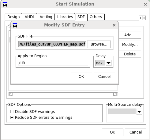
Figure 1 SDF setup
Pressing OK will start the simulation windows. In the “Objects” window right-click anywhere and select <Add to –> Wave –> Signals in Region> this should add your main signals to the “wave” screen. Finally, from the drop-down menus go to <Simulate –> Run –> Run -All>. Note the changes in the “wave” screen. Press “F” to fit all the signals in the screen. Finally, check the functionality to make sure that the synthesis was right. Also, zoom to the transitions and note the delays.